Design
Design Carbon Fiber Parts for CNC Machining
Design rules for CNC-machined carbon fiber parts covering geometry, fiber continuity, holes, tolerances and assembly interfaces.
Design Geometry for Reliable Machining
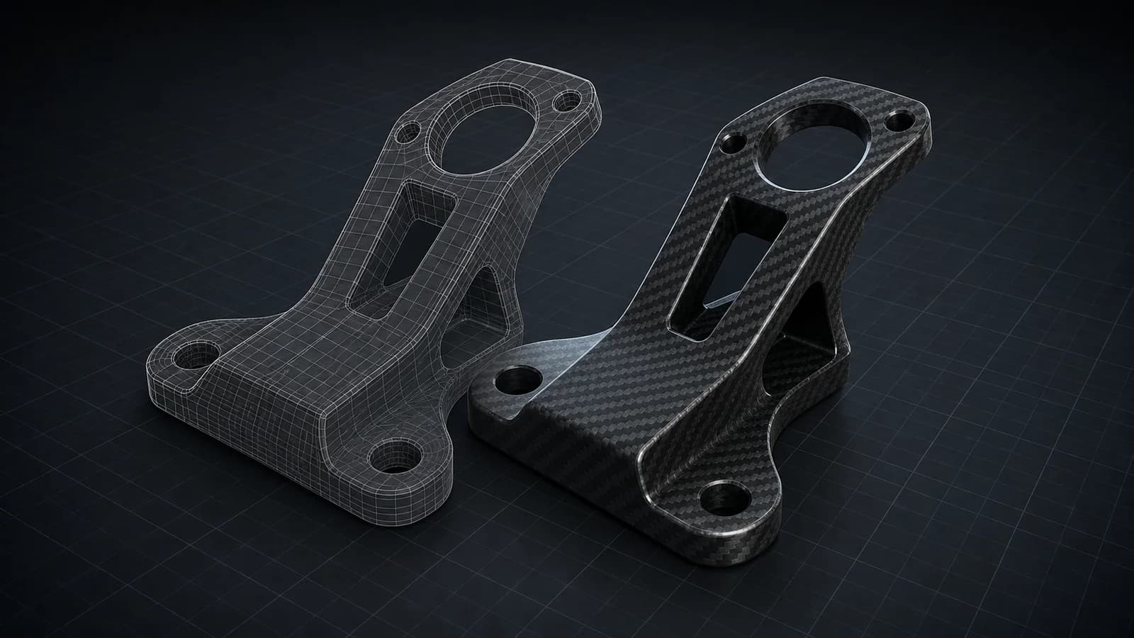
Use internal radii compatible with available tools and avoid fragile points, extremely narrow webs and abrupt section changes. Provide enough surrounding material for workholding and stable finishing cuts.
Closed slots, small holes and deep countersinks need specific review. A simpler contour may improve edge quality, shorten cycle time and reduce tool changes without changing product function.
Protect Fiber Continuity and Edges
Every cut interrupts reinforcing fibers. Place holes and slots away from highly loaded edges where possible, preserve adequate ligament width and align the laminate design with the principal load path.
Machined edges can expose fibers and resin. Define whether edges require sealing, chamfering or cosmetic finishing, and avoid relying on a thin unsupported edge for impact or bearing loads.
Holes, Fasteners and Inserts
Define fastener type, clamp load, washer area and expected load transfer. Countersinks remove more laminate near the surface and may require additional thickness or a different joint concept.
Bonded or mechanical inserts can spread concentrated loads, but their geometry, surface preparation and isolation from conductive carbon fibers must be considered as one assembly system.
Datums, Tolerances and Drawing Clarity
Use functional datums and apply tight tolerances only to interfaces that need them. Avoid stacking multiple dimensions that control the same feature in conflicting ways.
Identify units, material, thickness, cosmetic face, edge finish and inspection priorities. Pair the CAD model with a controlled drawing when tolerances or notes cannot be communicated by geometry alone.
Frequently Asked Questions
What is the most common design mistake?
Treating CFRP like a uniform metal plate. Fiber direction, edge distance, bearing and delamination risk should be considered from the first layout.
Are sharp internal corners possible?
Machined internal corners inherit the cutter radius. Very small radii may require small, less robust tools or secondary processes, so specify only what the assembly needs.